


- Description
- Reviews
- FAQs
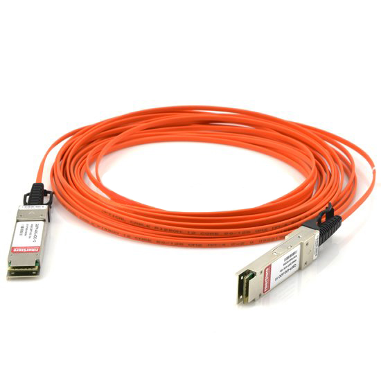
What is QSFP+ 40G ESR4 850nm 300m Optical Transceiver Module QSFP-40G-ESR4
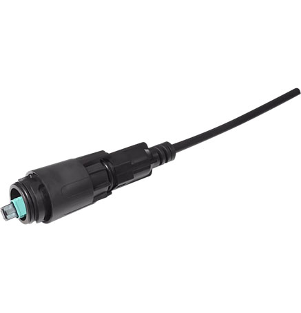
QSFP+ 40G ESR4 850nm 300m Optical Transceiver Module QSFP-40G-ESR4 is a Four-Channel, Pluggable, Parallel, Fiber-Optic QSFP+ Transceiver for InfiniBand QDR/DDR/SDR,12G/10G/8G/4G/2G fiber channel, PCIe and SAS Applications.The QSFP full-duplex optical module offers 4 independent transmit and receive channels, each capable of 11.3Gbps operation for an aggregate data rate of 45.2Gbps 300m using OM3 fiber. These modules are designed to operate over multimode fiber systems using 850nmVCSEL laser array.An optical fiber ribbon cable with an MPO/MTPTM connector can be plugged into the QSFP module receptacle.QSFP+ eSR4 is one kind of parallel transceiver which provides increased port density and total system cost savings.
Product Features
· Four-channel full-duplex transceiver modules
· Transmission data rate up to 11.3Gbit/s per channel
· Up to 300m on OM3 Multimode Fiber (MMF)
· Low power consumption <1.5W
· Operating case temperature: 0 to 70℃
· 3.3V power supply voltage
· Hot Pluggable QSFP form factor
· MPO connector receptacle
· Built-in digital diagnostic function
Applications
· Proprietary High Speed Interconnections
· Infiniband QDR and DDR interconnects
· Data Center
Regulatory Compliance
| Feature | Standard | Performance |
| Electromagnetic Interference (EMI) | FCC Part 15 Class B EN 55022:2010, Class B | Compatible with standards |
| Electromagnetic susceptibility (EMS) | EN 55024:2010 | Compatible with standards |
| Laser Eye Safety | FDA 21CFR 1040.10 and 1040.11 EN60950, EN (IEC) 60825-1,2 | Compatible with Class I laser product |
Absolute Maximum Ratings
The operation in excess of any absolute maximum ratings might cause permanent damage to this module.
| Parameter | Symbol | Min | Max | Unit | Notes |
| Storage Temperature | TS | -40 | 85 | ℃ | |
| Operating Case Temperature | TOP | 0 | 70 | ℃ | |
| Power Supply Voltage | VCC | -0.3 | 3.6 | V | |
| Relative Humidity (non-condensation) | RH | 0 | 85 | % | |
| Input Voltage | Vin | -0.3 | Vcc+0.3 | V |
Recommended Operating Conditions and Power Supply Requirements
| Parameter | Symbol | Min | Typical | Max | Unit | Notes |
| Operating Case Temperature | TOP | 0 | 70 | ℃ | ||
| Power Supply Voltage | VCC | 3.135 | 3.3 | 3.465 | V | |
| Power Consumption | 1.5 | W | ||||
| Data Rate | DR | 10.3125 | 11.3 | Gbps | ||
| Data Speed Tolerance | DR | -100 | +100 | ppm | ||
| Link Distance with OM3 fiber | D | 0 | 300 | m |
Electrical Characteristics
The following electrical characteristics are defined over the Recommended Operating Environment unless otherwise specified.
| Parameter | Test Point | Min | Typical | Max | Unit | Notes |
| Differential input impedance | Zin | 90 | 100 | 110 | ohm | |
| Differential Output impedance | Zout | 90 | 100 | 110 | ohm | |
| Differential input voltage amplitude | ΔVin | 300 | 1100 | mVp-p | ||
| Differential output voltage amplitude | ΔVout | 500 | 800 | mVp-p | ||
| Bit Error Rate | BR | E-12 | ||||
| Input Logic Level High | VIH | 2.0 | VCC | V | ||
| Input Logic Level Low | VIL | 0 | 0.8 | V | ||
| Output Logic Level High | VOH | VCC-0.5 | VCC | V | ||
| Output Logic Level Low | VOL | 0 | 0.4 | V | ||
Optical Characteristics
All parameters are specified under the recommended operating conditions with PRBS31 data pattern unless otherwise specified.
| Parameter | Symbol | Min | Typical | Max | Unit | Notes |
| Transmitter | ||||||
| Center Wavelength | λC | 840 | 860 | nm | 1 | |
| RMS Spectral Width | λrms | 0.4 | nm | 1 | ||
| Average Launch Power, each lane | PAVG | -7 | 2.3 | dBm | ||
| Optical Modulation Amplitude (OMA) | POMA | -5 | 0 | dBm | 1 | |
| Difference in Launch Power between any two lanes | Ptx,diff | 4.0 | dB | |||
| Launch Power in OMA minus Transmitter and Dispersion Penalty (TDP), each Lane | OMA-TDP | -6.5 | dB | 1 | ||
| Rise/Fall Time | Tr/Tf | 50 | ps | |||
| Extinction Ratio | ER | 3.5 | dB | |||
| Transmitter Eye Mask Margin | EMM | 10 | % | 2 | ||
| Average Launch Power OFF Transmitter, each Lane | Poff | -30 | dBm | |||
| Transmitter Eye Mask Definition {X1, X2, X3, Y1, Y2, Y3} | {0.23, 0.34, 0.43, 0.27, 0.35, 0.4} | |||||
| Receiver | ||||||
| Center Wavelength | λC | 840 | 850 | 860 | nm | |
| Damage Threshold | THd | 3.4 | dBm | |||
| Overload, each lane | OVL | 2.4 | dBm | |||
| Receiver Sensitivity in OMA, each Lane | SEN | -9.5 | dBm | |||
| Signal Loss Assert Threshold | LOSA | -30 | dBm | |||
| Signal Loss Deassert Threshold | LOSD | -12 | dBm | |||
| LOS Hysteresis | LOSH | 0.5 | 8 | dB | ||
| Optical Return Loss | ORL | -12 | dBm | |||
Notes:
1. Transmitter wavelength, RMS spectral width and power need to meet the OMA minus TDP specs to guarantee link performance.
2. The eye diagram is tested with 1000 waveform.
Digital Diagnostic Functions
Digital diagnostics monitoring function is available on all Wolon QSFP+ eSR4. A 2-wire serial interface provides user to contact with module. The structure of the memory is shown in Figure 3. The memory space is arranged into a lower, single page, address space of 128 bytes and multiple upper address space pages. This structure permits timely access to addresses in the lower page, such as Interrupt Flags and Monitors. Less time critical time entries, such as serial ID information and threshold settings, are available with the Page Select function. The interface address used is A0xh and is mainly used for time critical data like interrupt handling in order to enable a one-time-read for all data related to an interrupt situation. After an interrupt, IntL, has been asserted, the host can read out the flag field to determine the affected channel and type of flag.
| Parameter | Symbol | Min | Max | Unit | Notes |
| Temperature monitor absolute error | DMI_Temp | -3 | +3 | ℃ | Over operating temperature range |
| Supply voltage monitor absolute error | DMI_VCC | -0.1 | +0.1 | V | Over full operating range |
| Channel RX power monitor absolute error | DMI_RX | -3 | +3 | dB | |
| Channel Bias current monitor | DMI_Ibias | -10% | +10% | mA |
- Customers Reviews
-
 (0)
(0) (0)
(0) (0)
(0) (0)
(0) (0)
(0)
* Delivery Time.
We need 1-2 days to process your order before shipping. There are two shipping methoed.
Fast Delivery: The delivery time for US, European countries the delivery will take 3-5 days.
Slow Delivery: The delivery time for US, European countries the delivery will take 7-15 days.
* Tracking information.
After we ship package, customer receive automatic email with tracking details.
* Lost Package Policy.
If a package did not arrive in 2 weeks after the shipping date, then this package is treated as Lost. In this case a new package will be shipped to the customer provided we are able to give the same items as those purchased by the customer. If we are not able to provide the same items to substitute the lost ones we will either propose to the customer similar items or refund their cost as it will be mutually agree with the customer. If one or more items neither the same nor similar are available to be shipped, the customer can request to cancel the order entirely, thus the total cost of the order including shipping and handling cost will be fully refunded.


