


- Description
- Reviews
- FAQs
With bandwidth demands continuing to grow, higher and higher capacity and throughput are required in the data center. And to address these needs efficiently and effectively, a strategic approach focusing on existing user expectations and future capacity requirements is wanted. MTP/MPO cable is the good choice that can meet various network requirements. This post will list the roles of different MTP/MPO cables (MTP trunk, MTP harness, MTP conversion harness) in 10G/40G/100G migration.10G/40G/100G Migration Solutions
For upgrading connection data rates, several common scenarios are available with using MTP/MPO fiber cables. Following part will list these applications out for your reference.10G to 40G: 8-Fiber MTP Harness Cable
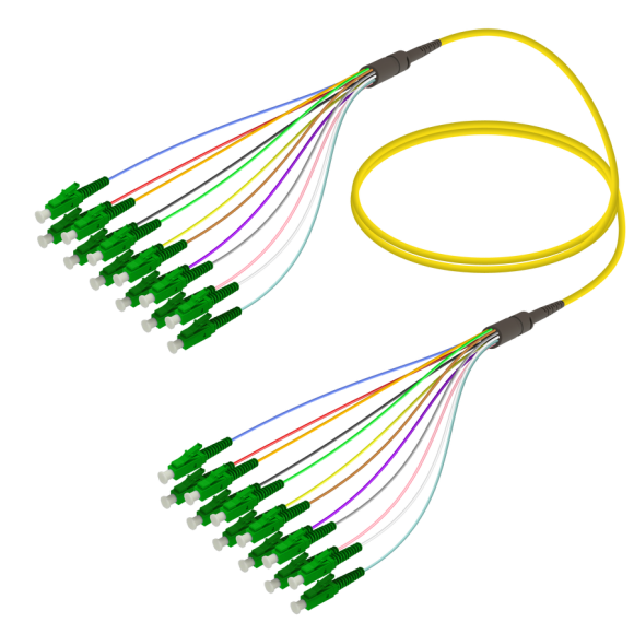
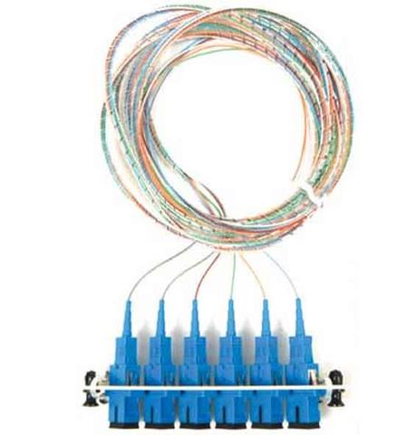
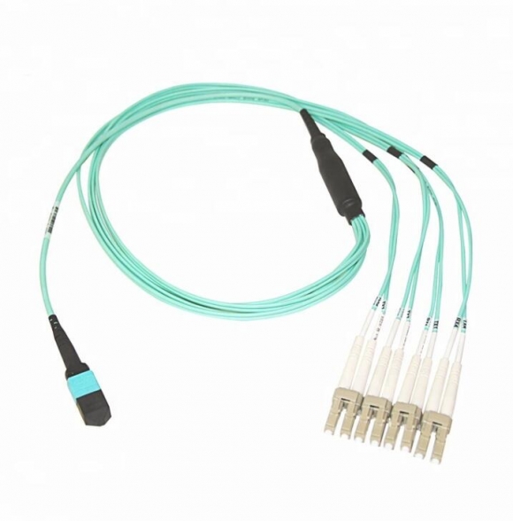
One commonly used upgrade possibility beyond 10G incorporates four 10G SFP+ transceiver connections to a 40G QSFP+, which requires a 8-fiber MPO-LC harness cable. Figure 1 illustrates one side of the transmission path utilizing this MPO harness cable in conjunction with a 40G QSFP+ to aggregate four 10G SFP+ transceivers. QSFP+ transceivers on the switches yield higher port densities and throughput.
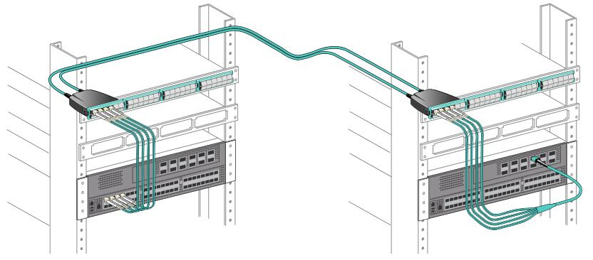
Figure 1: 10G to 40G upgrade by using MTP/MPO LC harness cable40G to 40G: 12-Fiber MTP Trunk Cable
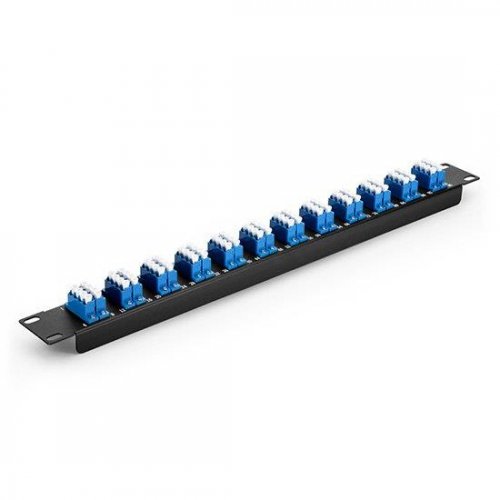
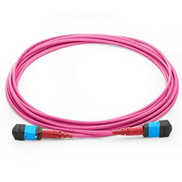
MTP trunk cable incorporates interconnected banks of QSFP+ transceivers (MPO to MPO connectivity). Figure 2 illustrates the connectivity. In this connection, 12-fiber MPO trunk cables are needed to connect the transceivers. Four fibers transmit light, four receive and four unused.
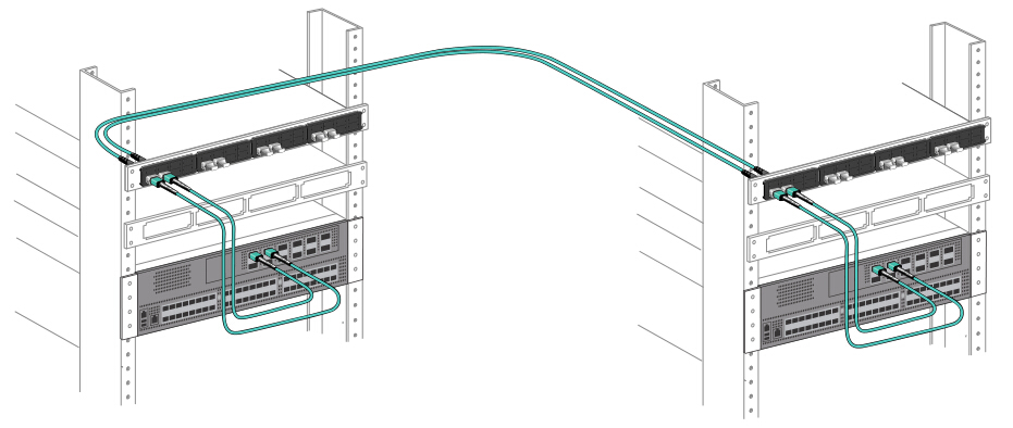
Figure 2: 40G to 40G connection by using MTP/MPO trunk cable with four fibers unused40G to 40G: 2×3 MTP Conversion Harness/Module
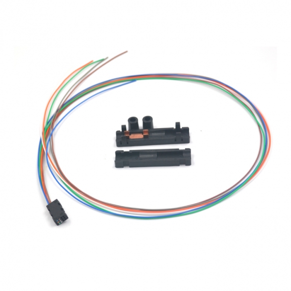
MTP conversion harness and MTP conversion module both take advantage of 100% fiber utilization. For those needing 100% fiber utilization, 2×3 MTP conversion harness or conversion module can achieve the purpose. Connectivity of the 2×3 MTP conversion harness and conversion module is the same. They are interchangeable, but must be used in pairs: one (MTP conversion harness or module) at each end of the link. Figure 3 shows an example of how MTP conversion module uses all fibers to achieve 100% fiber utilization. The eight live fibers from each of the three QSFP+ transceivers are transmitted through the trunks using the full 24 fibers. The second 2×3 conversion module unpacks these fibers to connect to the 3 QSFP+ transceivers on the other end.
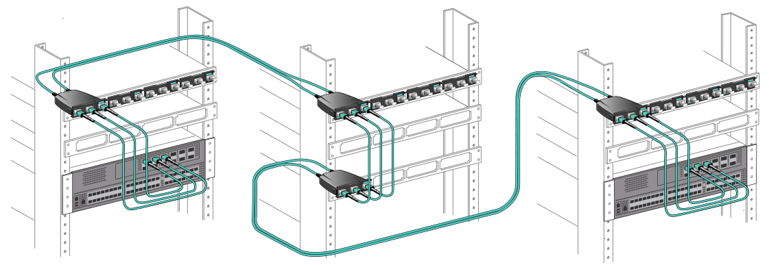
Figure 3: 40G to 40G connection with MTP conversion module ensuring 100% fiber utilization100G to 100G: MTP Trunk Cable
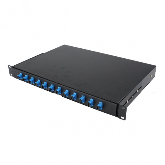
READ MORE ...What Is Plastic optical fiberFor 100G to 100G connection, 24-fiber MTP trunk cable allows direct attach capability of 100GBASE-SR10 CXP or CFP equipped devices, while 12-fiber MTP trunk cable can be used to allow the direct connection for 100G QSFP28 (MPO to MPO) connection.
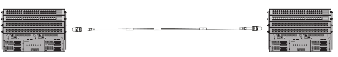
Figure 4: MTP trunk cable for 100G to 100G connection10G to 100G/120G: 24-Fiber MTP Harness Cable
To achieve 10G to 100G/120G connection, one popular implementation is to use the high density 100G/120G CXP for space-saving. This deployment can leverage the 10G-per-lane channels to distribute the 10G data anywhere in the data center. Figure 5 uses a 24-fiber MTP harness cable that separates each TX and RX pair, allowing connectivity to any duplex path reachable by a patch panel. Simply connect this cable to a 120G CXP transceiver and the customer can access the 12 individual transceiver pairs. When used with a patch panel, this method offers the ultimate in flexibility, allowing connectivity to any row, rack, or shelf.
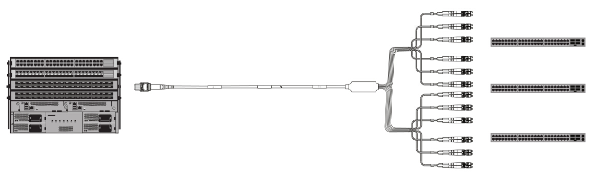
Figure 5: 10G to 100G connection by using 24-fiber MTP LC harness cable40G to 120G: 1×3 MTP Conversion Harness
One way to break out a 120G CXP is to use 1×3 MTP conversion harness cable. Figure 6 shows a 24-fiber fanout that utilizes 24 fibers to split the 12 transceivers into three groups of eight. These eight-fiber groups match the TX/RX fibers used on a QSFP+ transceiver for direct connection to three separate QSFP+ transceivers. Like the 12x10G segregation mentioned above, once split, the 3×8-fiber QSFP+ channels can be distributed through patch panels and 12-fiber based trunking to any area of the data center.
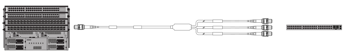
Figure 6: 40G to 120G connection by using 1×3 MTP conversion harnessSummary
READ MORE ...Ethernet vs. FiberSeveral solution scenarios have been illustrated in this post. From 10G to 40G/100G/120G, we can see that different MTP/MPO fiber cables are used for data transmission. Generally, MTP/MPO trunk cables are used for direct connection between two switches. MTP harness cables are used for data migration to higher data rates. And MTP/MPO conversion cables are used to achieve 100% fiber utilization between two switches. All of those different MTP/MPO fiber cables (MTP trunk, MTP harness, MTP conversion harness) can be found in SUNMA
- Customers Reviews
-
 (0)
(0) (0)
(0) (0)
(0) (0)
(0) (0)
(0)
* Delivery Time.
We need 1-2 days to process your order before shipping. There are two shipping methoed.
Fast Delivery: The delivery time for US, European countries the delivery will take 3-5 days.
Slow Delivery: The delivery time for US, European countries the delivery will take 7-15 days.
* Tracking information.
After we ship package, customer receive automatic email with tracking details.
* Lost Package Policy.
If a package did not arrive in 2 weeks after the shipping date, then this package is treated as Lost. In this case a new package will be shipped to the customer provided we are able to give the same items as those purchased by the customer. If we are not able to provide the same items to substitute the lost ones we will either propose to the customer similar items or refund their cost as it will be mutually agree with the customer. If one or more items neither the same nor similar are available to be shipped, the customer can request to cancel the order entirely, thus the total cost of the order including shipping and handling cost will be fully refunded.


